Home Measurement Technology Pressure transducer 

Pressure measurement for air and gases

Electrical pressure sensors

With differential pressure methods, the flow rate follows from the differential pressure across the flow element; the density of the gas also requires static pressure, temperature and, for air, humidity. We supply sensors for differential, gauge and absolute pressure as single sensors, and the PDP2.flange, which measures differential and static pressure in one housing. Selection criteria are measuring range, response time and overload resistance.

Electrical pressure sensors
  • ±1 mbar smallest differential pressure range of the PDP2.flange – for differential pressure measurement on laminar flow elements
  • 10 bar static pressure against atmosphere that the differential pressure cell of the PDP2.flange withstands, even in the ±1 mbar range
  • 1 kHz measuring and output rate for fast pressure changes

The pressure sensors at a glance

Select a model – the window shows data, documents and the request form.

  • PDP2.flange

    Differential and static pressure in one housing, read out over one MODBUS® connection

    Differential pressure
    ±1 / 2 / 10 / 20 mbar
    Static pressure
    −1 – +7 bar gauge · 0 – 7 bar absolute
    Linearity deviation
    typ. ±0.025 % of span
  • Combined, analogue

    PDP-classic

    The first generation of the combined transducer for differential and static pressure

    Differential pressure
    1 / 2 / 10 / 20 mbar
    Static pressure
    0.07 – 7 bar gauge · 1 – 7 bar absolute
    Response time (analogue)
    T90 approx. 5 ms
  • Differential pressure, analogue

    DPS.flange

    Purely analogue differential pressure sensor in a flange housing for leak testing applications

    Measuring ranges
    ±1 / 2 / 10 / 20 mbar
    Linearity
    typ. 0.75 % FS
    Output
    −2 – +2 V, M8 4-pin
  • Gauge and absolute pressure

    ATM

    Universal analogue pressure sensor with stainless steel isolating diaphragm, in many versions and accuracy classes

    Measuring ranges
    100 mbar – 100 bar
    Linearity
    ±0.5 / 0.25 / 0.1 % FS
    Response time (analogue)
    T90 1 ms
  • Digital, networkable

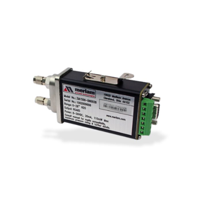
    M1500

    Microprocessor-based pressure transmitter for differential, gauge and absolute pressure with digital interface

    Measuring ranges
    25 mbar – 200 bar
    Accuracy
    better than ±0.025 to ±0.1 % FS
    Interfaces
    RS-232, RS-485 or USB
  • HART, high overload

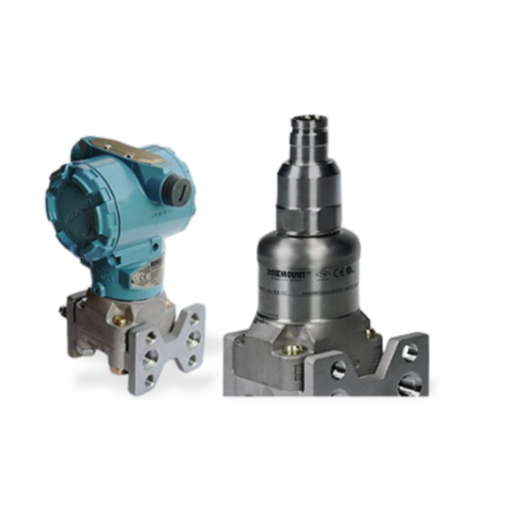
    3051S

    Transmitter for differential, gauge and absolute pressure with HART protocol and stainless steel isolating diaphragm

    Overload limit
    100 bar
    Accuracy
    ±0.025 – ±0.1 % FS
    Output
    4 – 20 mA with HART

Electrical pressure sensor

PDP2.flange

PDP2.flange
Differential pressure
±1 / 2 / 10 / 20 mbar
Static pressure
−1 – +7 bar gauge · 0 – 7 bar absolute
Linearity deviation
typ. ±0.025 % of span

Overview

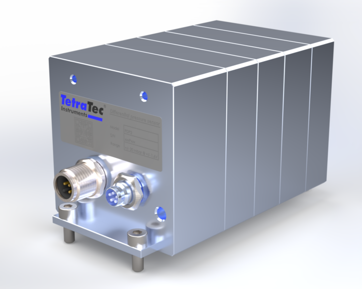
The PDP2.flange is a digital combined pressure transducer for differential and static pressure in a flange housing. It is designed for flow measurement with a laminar flow element.

The differential pressure cell works capacitively: a stainless steel diaphragm, clamped between two ceramic half-shells with fixed electrodes, separates the two pressure chambers, and its deflection changes the capacitances against the two electrodes. The static pressure cell works piezoresistively. The transducer supplies the temperature-compensated values of both cells over MODBUS RTU and additionally as an analogue signal per measured variable.

Main features

  • One measuring point for two quantities: no second adapter, no second cable
  • Flange-mounted directly on a manifold plate or LFE, without hose connection
  • No sealing liquid between medium and diaphragm
  • Internal volumes reduced to a minimum
  • Any measuring range within the span of a differential pressure cell can be set, e.g. 0 to 20 mbar with the ±20 mbar cell

Three versions

Same flange housing, same cells and interfaces; the version determines which measured variables are fitted. For every version there is a connection plate with G1/8" ports to every sensor connection.

  1. Differential and static pressure

    PDP2.Combi

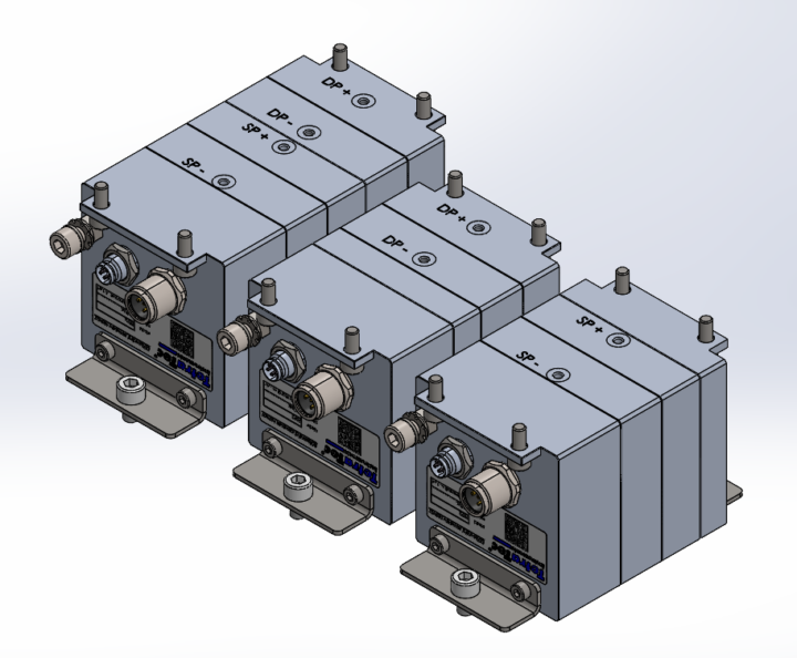
    Both cells in one housing, four pressure connections DP+, DP−, SP+ and SP− on the flange face.

    • Order example PDP2.flange 070r10
    • Connection plate PDP2-VT-KO
  2. Differential pressure only

    PDP2.DP

    Only the capacitive differential pressure cell, pressure connections DP+ and DP−.

    • Order example PDP2.flange 000n20
    • Connection plate PDP2-VT-DP
  3. Static pressure only

    PDP2.SP

    Only the piezoresistive static pressure cell, as gauge or absolute pressure, pressure connections SP+ and SP−.

    • Order example PDP2.flange 010a00
    • Connection plate PDP2-VT-SP

Technical data

Measuring ranges, differential pressure
−1 – +1 · −2 – +2 · −10 – +10 · −20 – +20 mbar
Measuring ranges, static pressure, gauge
−1 – +1 bar · −1 – +7 bar
Measuring ranges, static pressure, absolute
0 – 1 bar · 0 – 7 bar
Measuring principle
Differential pressure: capacitive
static pressure: piezoresistive
Materials in contact with the medium
Differential pressure cell: ceramic, nickel-iron alloy, chromated aluminium
static pressure cell: stainless steel 316 L, chromated aluminium
Linearity deviation
typ. ±0.025 % of span (both cells)
Hysteresis
differential pressure typ. 0.025 % · static pressure typ. 0.010 % of span
Repeatability
typ. 0.010 % of span (both cells)
Response time
T90 approx. 40 ms (both cells)
Position dependency (differential pressure)
0.05 % of span
Static pressure influence
0.3 Pa per bar
Warm-up time
differential pressure typ. 30 min · static pressure typ. 15 min
Pressure against atmosphere (differential pressure cell)
up to 10 bar gauge
Overload limit
Differential pressure: plus to minus 10 bar, minus to plus < 1 bar
static pressure: 2 × measuring range
regular changes in the sign of the pressure load: increased zero drift
Operating temperature / temperature compensation
+15 – +50 °C
Storage temperature
−20 – +60 °C
Operating direction
bidirectional
Mounting position
any; carry out a zero adjustment after changing the position
Media
Air and inert gases, non-condensing
not permissible: liquids, aggressive and corrosive gases, condensing media
must not be flushed
Housing / protection class
anodised aluminium · IP 64
Weight
PDP2.Combi 540 g · PDP2.DP 400 g · PDP2.SP 380 g
Pressure connection
flange face, O-ring 3.5 × 1.5 mm, M3 internal thread
tightening torque M4 max. 2.9 Nm
Power supply
24 VDC ±20 %, current consumption ≤ 30 mA
Electrical connection
digital: M12×1 panel connector, 5-pin
analogue: M8×1 panel connector, 5-pin
Digital output signal
MODBUS RTU over RS-485 (MODBUS Application Protocol V1.1b3, MODBUS over Serial Line V1.02)
Bus parameters
1,200 – 230,400 Bd (factory setting 115,200 Bd) · address 1 – 247 · parity none, even (factory), odd · 1 (factory) or 2 stop bits · bus termination switchable in the device
Data format
Float32 and Float64 to IEEE 754, uint16, uint32, uint64 · byte order big-endian (factory) or little-endian, also with byte swap · time stamp per measured variable, resolution 0.1 ms
Sampling rate / filter
5, 10, 16, 20, 50 (factory), 60 readings/s · Sinc1 – Sinc4 (factory Sinc3)
Analogue output signal
−2 – +2 V per measured variable
Accessories
Connection cable M12×1, straight (LTG-MBUS-GK125A-050U-00ADER) or angled (LTG-MBUS-WK125A-050U-00ADER), 5 m
connection cable M8×1 shielded, straight (LTG-PDP2-GK085B-050U-00ADER) or angled (LTG-PDP2-WK085B-050U-00ADER), 5 m
factory calibration certificate

Your request

Select what applies – your selection is then entered in your message in the contact form.

  1. Version
  2. Differential pressure rangecan be set within the span of a cell, e.g. 0 to 20 mbar
  3. Static pressure range
  4. Static pressure as
  5. Medium
  6. Accessories

Electrical pressure sensor

PDP-classic

PDP-classic
Differential pressure
1 / 2 / 10 / 20 mbar
Static pressure
0.07 – 7 bar gauge · 1 – 7 bar absolute
Response time (analogue)
T90 approx. 5 ms

Overview

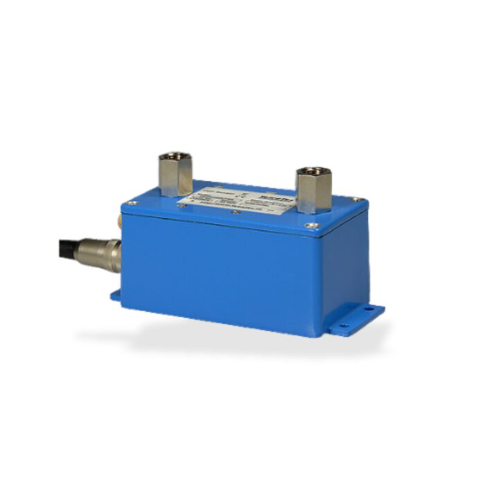
The PDP combines a differential pressure sensor with a static pressure sensor. It is designed for flow measurement with laminar flow elements.

The differential pressure is measured by a capacitive cell with high overload capacity, the static pressure by a piezoresistive sensor. Both cells respond quickly, are reproducible and show low hysteresis and a stable zero point.

Main features

  • Bidirectional differential pressure measurement as an option
  • Slip-on or flange housing
  • Signal conditioning with the S320 controller

Technical data

Measuring ranges, differential pressure
1 / 2 / 10 / 20 mbar
Measuring ranges, gauge pressure
0.07 / 0.35 / 1 / 2 / 4 / 7 bar
Measuring ranges, absolute pressure
1 / 2 / 4 / 7 bar
Linearity
Differential pressure typ. ±0.5 % FS
gauge and absolute pressure typ. ±0.1 % FS
Repeatability / hysteresis
±0.05 % FS each
Response time (analogue)
T90 approx. 5 ms
Overload limits
Differential pressure: 8 bar static or as one-sided overpressure on the plus side, 5 × FS as one-sided overpressure on the minus side
gauge and absolute pressure: 2 × FS, max. 8 bar
Process connection
Slip-on housing: 2 × 1/4" NPT female, nickel-plated brass
flange housing: 2 × G 1/4" female, nickel-plated brass
Outputs
2 × voltage (−2 – +2 V) or 2 × current (4 – 20 mA)
Media
clean, dry, non-condensing, non-corrosive, non-flammable gases and air; air and inert gases up to 6 bar
Power supply
24 VDC (19 – 29 VDC), approx. 30 mA (RS485: approx. 50 mA)

Downloads

Your request

Select what applies – your selection is then entered in your message in the contact form.

  1. Medium
  2. Output signal
  3. Applicationoptional

Electrical pressure sensor

DPS.flange

DPS.flange
Measuring ranges
±1 / 2 / 10 / 20 mbar
Linearity
typ. 0.75 % FS
Output
−2 – +2 V, M8 4-pin

Overview

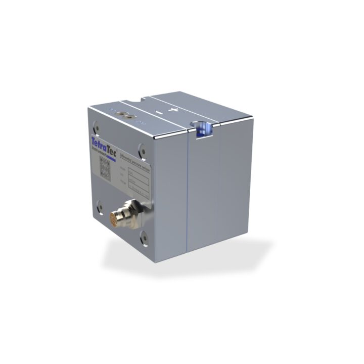
The DPS.flange measures differential pressure with a capacitive cell and outputs it purely analogue. The flange housing ensures a process-safe, tight connection.

The capacitive cell has a high overload resistance and responds quickly to pressure changes, which makes the sensor suitable for leak testing applications.

Main features

  • Reduced internal volume
  • Bidirectional operation
  • Including 5-point calibration record

Technical data

Measuring ranges
±1 / 2 / 10 / 20 mbar
Linearity
typ. 0.75 % FS
Repeatability
typ. 0.010 % FS
Hysteresis
typ. 0.012 % FS
Overload limits
6 bar from plus to minus
3 × FS from minus to plus
Process connection
flange with O-ring or screw connection with M3 thread
Electrical connection / output
M8, 4-pin, −2 – +2 V
Temperature range
+15 – +45 °C
Material
aluminium / ceramic
Media
air, inert gases, non-condensing
Power supply
24 VDC

Downloads

Your request

Select what applies – your selection is then entered in your message in the contact form.

  1. Medium
  2. Applicationoptional

Electrical pressure sensor

ATM

ATM
Measuring ranges
100 mbar – 100 bar
Linearity
±0.5 / 0.25 / 0.1 % FS
Response time (analogue)
T90 1 ms

Overview

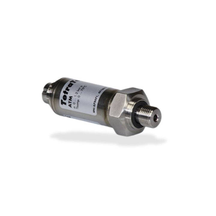
The ATM measures gauge, overpressure or absolute pressure. It is available with voltage or current output and with various electrical and pressure connections.

The ATM series is based on a piezoresistive sensor, which is separated from the measured medium by a stainless steel isolating diaphragm with oil filling. The robust, compact design allows use under adverse conditions.

Main features

  • Zero and span adjustable
  • Ranges from 25 to 1,000 bar only as overpressure or absolute pressure version
  • Medium temperature up to 150 °C as an option

Technical data

Measuring ranges
gauge −1 – 100 bar · absolute 0 – 100 bar
Linearity
±0.5 %, ±0.25 %, ±0.1 % FS
Repeatability / hysteresis
±0.05 % FS each
Response time (analogue)
T90 1 ms
Overload limit
3 bar, max. 3 × FS
Process connection
G 1/4 female, G 1/4 male, 1/4 NPT male, G 1/2 male
Electrical connection
DIN 43650, M12×1 4-pin, M16 5-pin
Output
0 – 10 V or 4 – 20 mA
Temperature range
0 – 70 °C, −40 – 150 °C
Material
stainless steel / titanium / Hastelloy
Media
gases, liquids, steam
Power supply
24 VDC (9 – 33 VDC), approx. 3 mA

Downloads

Your request

Select what applies – your selection is then entered in your message in the contact form.

  1. Measured variable
  2. Medium
  3. Output signal
  4. Applicationoptional

Electrical pressure sensor

M1500

M1500
Measuring ranges
25 mbar – 200 bar
Accuracy
better than ±0.025 to ±0.1 % FS
Interfaces
RS-232, RS-485 or USB

Overview

The M1500 digital pressure transmitter measures differential, gauge or absolute pressure. It is available with various interfaces and optionally with an analogue output.

The transmitter is configured and read out by PC via the digital interface; several transmitters can be networked via RS-485. In the version with analogue output, the digital interface is used for configuration only. The accuracy refers to the value at the digital interface.

Main features

  • Network operation of up to 32 transmitters (RS-485)
  • MSP protocol (Meriam Serial Protocol)
  • Temperature-compensated from −10 to 50 °C

Technical data

Measuring ranges
Differential pressure 0 – 5,000 mbar
gauge pressure −1 – 200 bar
absolute pressure 0 – 70 bar
Linearity
Differential pressure typ. ±0.025 % FS
gauge and absolute pressure typ. ±0.1 % FS
Repeatability / hysteresis
±0.05 % FS each
Overload limits
Differential pressure: 2 × FS as one-sided overpressure on the plus side, 10 bar static with pressure on both sides
gauge and absolute pressure: 2 × FS
Process connection
Slip-on housing: 2 × 1/4" NPT female, nickel-plated brass
flange housing: 2 × G 1/4" female, nickel-plated brass
Outputs
2 × voltage (−2 – +2 V) or 2 × current (4 – 20 mA) or 1 × serial data (RS485)
Media
clean, dry, non-corrosive, non-flammable gases and air
Power supply
24 VDC (17 – 32 VDC)

Downloads

Your request

Select what applies – your selection is then entered in your message in the contact form.

  1. Measured variable
  2. Medium
  3. Output signal
  4. Applicationoptional

Electrical pressure sensor

3051S

3051S
Overload limit
100 bar
Accuracy
±0.025 – ±0.1 % FS
Output
4 – 20 mA with HART

Overview

The 3051S measures differential, gauge or absolute pressure and transmits the reading as a 4 to 20 mA current signal with HART protocol.

The measuring span can be set bidirectionally and continuously with a HART communicator. The capacitive sensor is isolated from the medium by a stainless steel isolating diaphragm with oil filling; the oil filling and built-in protective mechanisms result in the high one-sided overload resistance, particularly for differential pressure.

Main features

  • Optionally with LCD display and keys for zero and span (PlantWeb)
  • 16-bit resolution
  • Available in numerous versions

Technical data

Measuring ranges
Differential pressure 0.25 – 138 bar
gauge pressure 0 – 138 bar
absolute pressure 0 – 276 bar
Accuracy
±0.025 – ±0.1 % FS depending on span; < 0.1 % FS
Overload limit
100 bar
Process connection
1/4" NPT female on the flange
Electrical connection
terminals inside the housing
Media
air, gases, liquids, vapour, also corrosive or aggressive

Downloads

Your request

Select what applies – your selection is then entered in your message in the contact form.
  1. Measured variable
  2. Medium
  3. Applicationoptional

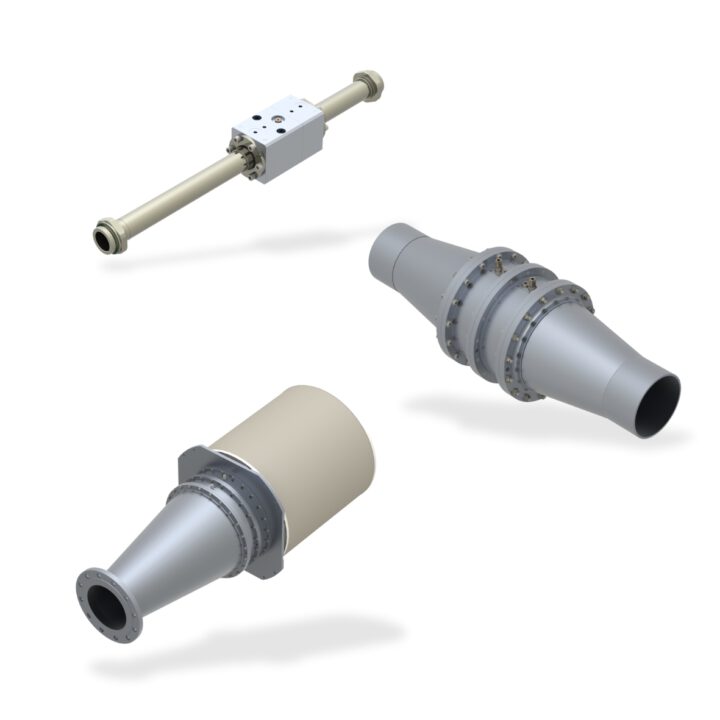
For a complete measuring section

Together with a laminar flow element, temperature and humidity sensors and an evaluation unit, pressure sensors form the measuring section. Calibration is carried out by our calibration laboratory.