Home Measurement Technology Critical flow nozzles 

Flow standards for air and gases

Critical nozzles

In critical operation the gas reaches the speed of sound in the narrowest cross-section of the nozzle; the volume flow then remains constant. Critical nozzles thus set the flow of air and pure gases for recurring calibration tasks and serve as a transfer standard for gas meters, LFEs, mass flow meters and other flow meters. We supply them as single nozzles, in adapters, as nozzle metering sections and in nozzle galleries.

Critical nozzles
  • ISO 9300 We manufacture Venturi nozzles to DIN EN ISO 9300 and micro nozzles with smaller throat diameters in line with the standard.
  • DN 4 – 400 nominal pipe sizes from the single nozzle to the nozzle metering section and nozzle gallery.
  • 10 years recalibration interval at best for Q ≥ 2 Nm³/h, 5 years for Q < 2 Nm³/h (standard conditions 1,000 mbar, 20 °C, 0 % RH) – nozzles have no moving parts.

The models at a glance

Open a model for data, versions and request.

  • Critical nozzles

    Venturi and micro nozzles for inlet nominal sizes up to DN 400.

    Flow rate
    0.6 L/h – 6,000 m³/h
    Throat diameter
    10 µm – 100 mm
    Inlet pressure
    1 – 7 bar abs.
  • Single metering section

    Single nozzle adapters

    Small nozzles as a single metering section on standard pipes.

    Nominal size
    DN 4 – DN 10
    Flow rate
    up to approx. 6 m³/h
    Connection
    pipe adapter, compression or VCR fitting
  • Wide flow range

    Nozzle galleries SNG-30 and SNG-50

    One compact flow-setting system for many flow steps.

    Flow rate
    up to 15 m³/h
    Manifold
    DN 30 / DN 50
    Inlet pressure
    1 – 10 bar abs.

Common to all nozzles

Manufacturing tolerance
±5 % of set value (standard)
Calibration uncertainty (best possible)
±0.25 % of reading
Operating temperature
0 to +50 °C
Media
air and gases compatible with stainless steel
Material
stainless steel, other materials on request
Calibration
in pressure or suction operation, with air or pure gases
Calibration certificate
factory, DAkkS (D-K-17589-01-00) or PTB calibration
Critical nozzles
Flow rate
0.6 L/h – 6,000 m³/h
Throat diameter
10 µm – 100 mm
Inlet pressure
1 – 7 bar abs.

Overview

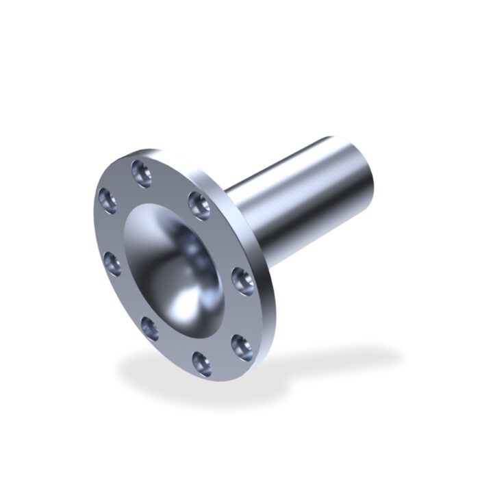
We manufacture Venturi nozzles and micro nozzles as single nozzles or as complete nozzle metering sections.

Suction operation is the preferred mode, as the atmospheric density at the inlet is very constant. In pressure operation the nozzle requires stable pressure control. For free, undisturbed inflow, no wall may come closer to the nozzle axis and the inlet plane than five times the throat diameter.

Main features

  • Suction or pressure mode
  • Connection via adapters, clamp connectors or flanges
  • No moving parts

Two nozzle types

The throat geometry depends on the throat diameter.

  1. to DIN EN ISO 9300

    Venturi nozzle

    Venturi nozzles, also known as Laval nozzles, have a flow-optimised inlet radius and outlet cone. This keeps the pressure loss low and the pressure recovery high: from a throat diameter of 1 mm they operate critically with a differential pressure of 120 to 200 mbar between inlet and outlet.

  2. in line with DIN EN ISO 9300

    Micro nozzle

    Up to a throat diameter of 170 µm, micro nozzles have a drilled, cylindrical throat geometry; a Venturi shape is only possible above that. They have almost no pressure recovery and only operate critically from a pressure ratio of 2 : 1 between inlet and outlet.

Technical data

Flow range
0.6 L/h to 6,000 m³/h (air equivalent)
Throat diameter d
Venturi nozzle: 170 µm to 100 mm
Micro nozzle: 10 µm to 170 µm
Inlet nominal size
Venturi nozzle: DN 15 to DN 400
Micro nozzle: DN 4 to DN 18
Geometry of Venturi nozzle
inlet radius 2 × d, outlet cone 8° full angle
Inlet pressure
1 to 7 bar absolute

Downloads

Your request

Select what applies – your selection is then entered in your message in the contact form.

  1. Model
  2. Medium
  3. Mode of operation
  4. Connection
  5. Calibration certificate
Single nozzle adapters
Nominal size
DN 4 – DN 10
Flow rate
up to approx. 6 m³/h
Connection
pipe adapter, compression or VCR fitting

Overview

Small nozzles are connected to standard pipes with commercially available compression fittings or simple pipe adapters.

Main features

  • For recurring calibration tasks on volume flow meters for air and gases
  • Nozzle O-ring sealed and plug-in, or metal-sealed in the sealing washer
  • Larger nozzles and flow rates as a nozzle section with flange connection

Configurations

Four configurations differ in sealing and connection.

  1. Pipe adapter

    Nozzle adapter 10-A-300-a

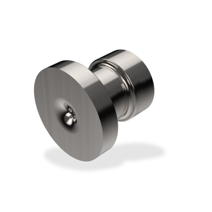
    Nozzle O-ring sealed, plug-in type in cylindrical pipe adapter 10-A-300-a or 10-A-301-a; threaded connection G1/8" or G1/4".

  2. Compression fitting

    CFO-SS-6MO-6 adapter

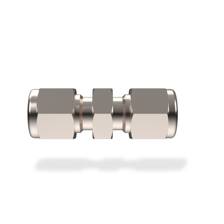
    Nozzle O-ring sealed, plug-in type in Swagelok adapter SS-6MO-6 or SS-400-6; connection via compression fitting or external thread.

  3. Metal seal

    CFO-4-VCR-7-4 adapter

    Nozzle integrated into the sealing washer, metal-sealed in Swagelok adapter 4-VCR-7-4 with union nut; internal or external thread.

  4. Welded in

    Nozzle adapter FRO

    Throttle or nozzle, e.g. welded into an SS-4-VCR fitting; with compression fitting and external thread.

Technical data

Nominal size
DN 4 to DN 10
Flow range
up to approx. 6 m³/h

Downloads

Your request

Select what applies – your selection is then entered in your message in the contact form.
  1. Medium
  2. Mode of operation
  3. Connection
  4. Calibration certificate

Critical nozzles

Nozzle galleries SNG-30 and SNG-50

Nozzle galleries SNG-30 and SNG-50
Flow rate
up to 15 m³/h
Manifold
DN 30 / DN 50
Inlet pressure
1 – 10 bar abs.

Overview

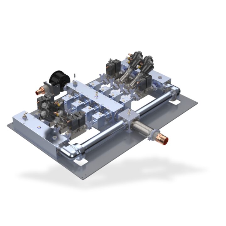
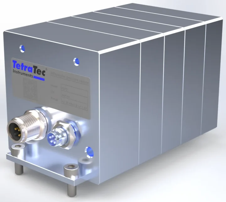
In the nozzle gallery (Sonic Nozzle Gallery), several binary-staged critical nozzles are connected in parallel and combined. This lets you set flow rates with the resolution of the smallest nozzle up to approximately twice the flow of the largest nozzle.

The nozzles usually follow a binary approach: they have 1, 2, 4 … 2ⁿ⁻¹ times the nominal flow Q1 of the smallest nozzle; combined, n nozzles give 2ⁿ − 1 flow steps. The gallery consists of the inlet block, the nozzle string with centre block and the outlet block and can be fully automated with pneumatically piloted valves. For larger flow rates we build nozzle galleries to your requirements with inlet and outlet sections, DIN flanges and butterfly valves in combined nominal sizes from DN 50 to DN 400.

Main features

  • Valves manually or pneumatically controlled
  • Block-and-bleed: 2 valves per nozzle string
  • 4 sensor connections: 2 × pressure, temperature, relative humidity
  • Throat diameter according to DIN EN ISO 9300 at least 4 to 10 times smaller than the inlet nominal size

Technical data

Flow range
SNG-30: up to 5 m³/h
SNG-50: up to 15 m³/h
air equivalent in each case
Manifold nominal size
SNG-30: DN 30
SNG-50: DN 50
Throat diameter
SNG-30: 10 µm to 3 mm
SNG-50: 10 µm to 5 mm
Equipment
4 critical nozzles; up to 9 connections for nozzle adapters, the one on the front face for the nozzle with the largest throat diameter
Inlet pressure
1 to 10 bar absolute
Manifold pressure rating
0 to 10 bar
Process connections
Inlet block: 2 × G3/4" (SNG-50: G1 1/2"), 3 × G1/2", 1 × G1/4" female thread
Outlet block: 2 × G3/4" (SNG-50: G1 1/2"), 2 × G1/2", 1 × G1/4" female thread
Centre block: 1 × G1/8" (SNG-50: G1/4") female thread

Downloads

Your request

Select what applies – your selection is then entered in your message in the contact form.
  1. Version
  2. Valves
  3. Medium
  4. Mode of operation
  5. Calibration certificate

From standard to calibration system

The nozzle gallery as a complete flow calibration system with controller and operation is the CoM4.Gallery; sensors for the gallery connections are listed under pressure and under temperature and humidity.